Optocouplers
An optocoupler, also called an opto-isolator, photocoupler, or optical isolator, is a component that transfers electrical signals between two isolated circuits by using light. An optocoupler consists of a light source (usually an LED) and a light sensor, both embedded in one package. It is used primarily for isolation rather than to switch a high current. It allows one section of a circuit to be electrically isolated from another and protects sensitive components, such as logic chips or a microcrontroller, from voltage spikes or incompatible voltages in other sections of a circuit.
Internally, and optocoupler works on the same principle as a solid-state relay. The input and output of the optocoupler are isolated from each other because the only internal connection is a light beam.
The primary purpose of an optocoupler is to provide protection against excessive voltage - from transients, incompatible power supplies, or equipment with unknown characteristics. A series resistor for the LED is usually not built into most optocouplers because the value of the resistor will depend on the input voltage that is used. For an optocoupler with an open-collector output, a pull-up resistor is necessary in most applications. The voltage from the optocoupler must be matched to the input requirements of other components, and the collector current must remain wihthin the specified limits.
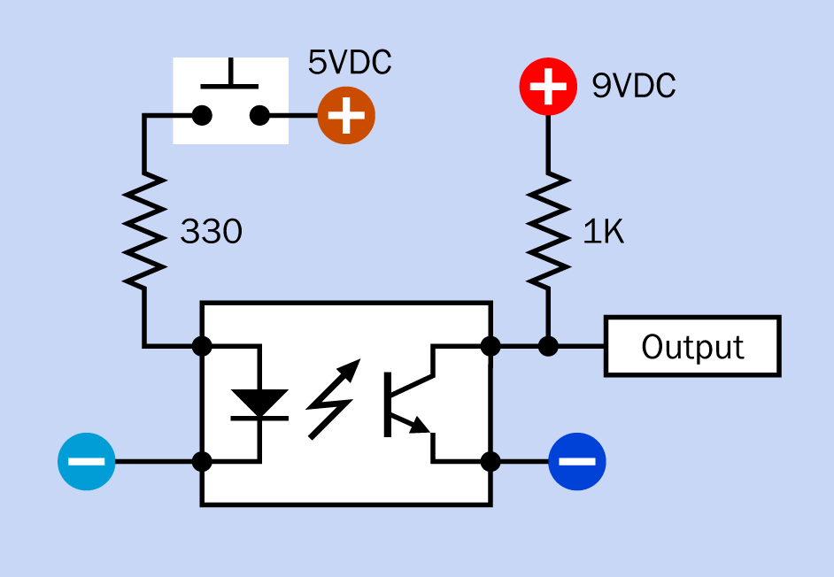
Figure 1: Typical values for a series resistor (to protect the LED) and pull-up resistor (to control current and voltage on the output side) in an optocoupler circuit.
Values
CTR(Current Transfer Ratio): The ratio of maximum ouput current to input current, expressed as a percentage.VCE(MAX): The maximum collector-emitter voltage difference (in an optocoupler with a bipolar phototransistor output). Values from 20 to 80 volts are common.VISO: The maximum potential difference, inVDC, between the two sides of the optocoupler.IMAX: The maximum current the transistor can handle, generally inmA.
4N35
Connection
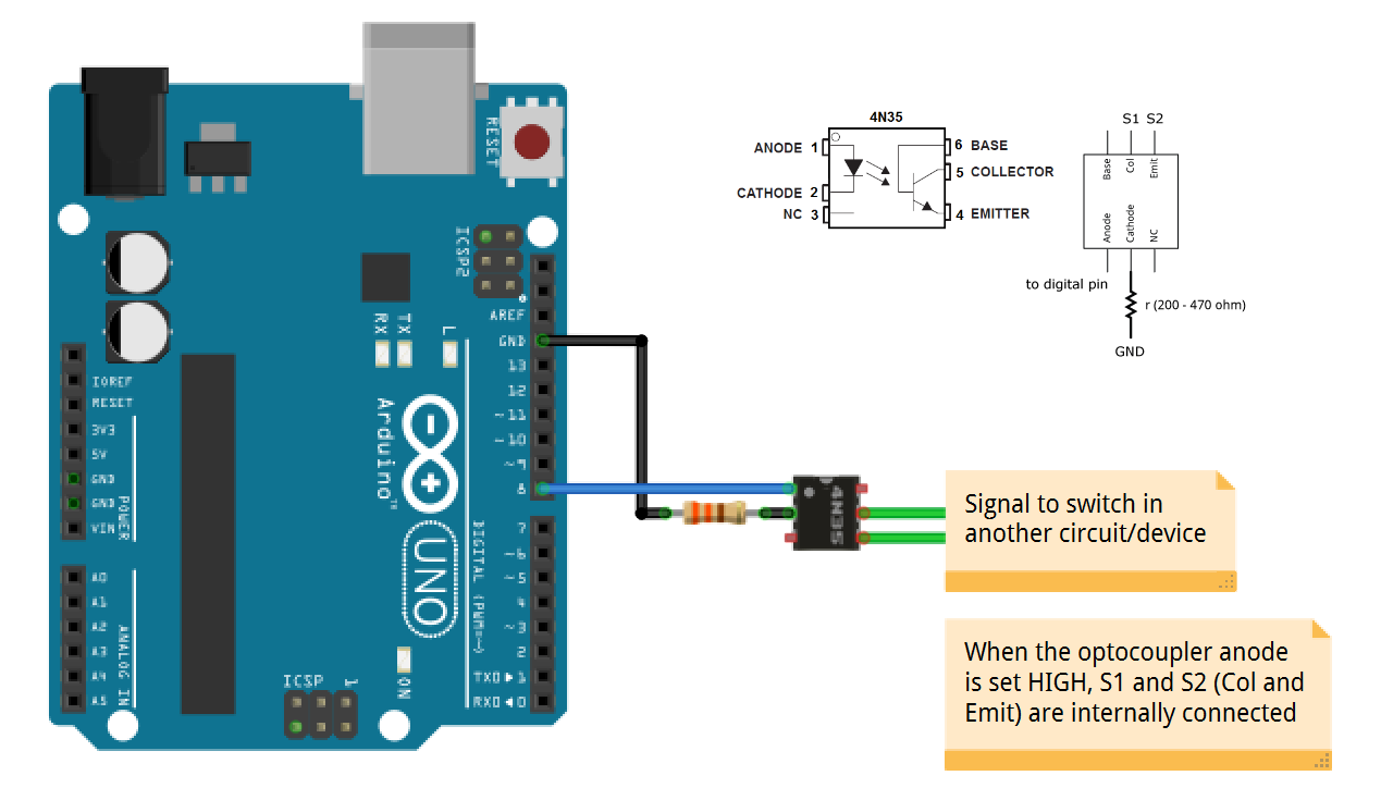
Sketch
int optocouplerPin = 8;

void setup()
{
    pinMode(optocouplerPin, OUTPUT);
}

void loop()
{
    digitalWrite(optocouplerPin, HIGH);
    delay(1000);
    digitalWrite(optocouplerPin, LOW);
    delay(1000);
}